Computer Vision Nodes in Stitch: ML Pipelines and the Bounding Box Debugging Story
Computer Vision Nodes in Stitch:
Building CoreML and Vision-powered detection nodes for a visual prototyping tool, and the investigation that fixed bounding box alignment.
What is Stitch?
Stitch is an open-source visual prototyping tool in the spirit of Origami Studio and Quartz Composer. Instead of writing code, designers and developers wire together nodes in a graph to build interactive prototypes. During my 2+ years on the project I built the computer vision pieces – CoreML and Vision-powered detection nodes, QR and face detection, and the coordinate-conversion plumbing that ties them to SwiftUI overlays. Active development on Stitch has since wound down; the code remains open source.
Why a Node-Based Tool is a Natural Fit for Computer Vision
A visual prototyping tool like Stitch is a natural fit for computer vision pipelines. The data flow maps directly: camera input goes in, ML inference happens in the middle, structured data comes out. I built a set of nodes so that a graph author can wire a camera feed into a CoreML node, fan the detection results out to overlay layers, and see bounding boxes or labels rendered on screen; allowing prototypers the ability to build a Computer Vision pipeline without writing code.
The challenge was making the coordinate math invisible. Vision frameworks output normalized coordinates, camera feeds arrive in pixel space, and SwiftUI layouts use their own coordinate system. The nodes need to handle all of that translation so the graph author only thinks about “camera in, detections out.”
Image Classification Node
The CoreMLClassificationNode accepts a Core ML model file plus a camera/image input and outputs detected labels, confidence scores, positions, and bounding boxes. Under the hood, a dedicated VisionOpActor runs VNCoreMLRequest on a background queue, reusing requests and keeping state actor-isolated for thread safety.
Here’s what it looks like in an actual graph - connected to a front-facing camera feed, running inference on a MobileNetV2 CoreML model, and displaying the inference results.
Object Detection Node
The object detection path uses the same camera-to-Core ML pipeline, but returns detections with class labels, confidence scores, locations, and bounding boxes. In this clip, the live camera feed detects objects on a table and renders labels and bounding boxes over the preview in full-screen mode. The default model the node ships with is YOLOv3Tiny.
QR Code Detection
The QRCodeDetectionNode wraps Vision’s barcode detection request (scoped to the .qr symbology) and returns a boolean detection flag, the decoded message, corner positions, and bounding box size. Like the CoreML node, it flips the Y-axis and translates bounding boxes to match Stitch’s coordinate system, making it trivial to drive highlights or UI prompts from QR scans.
The QR node shares the same coordinate conversion pipeline as the CoreML node, which was an early validation that the transformRect approach was general enough to serve as the standard conversion layer across all vision features.
Coordinate Conversion
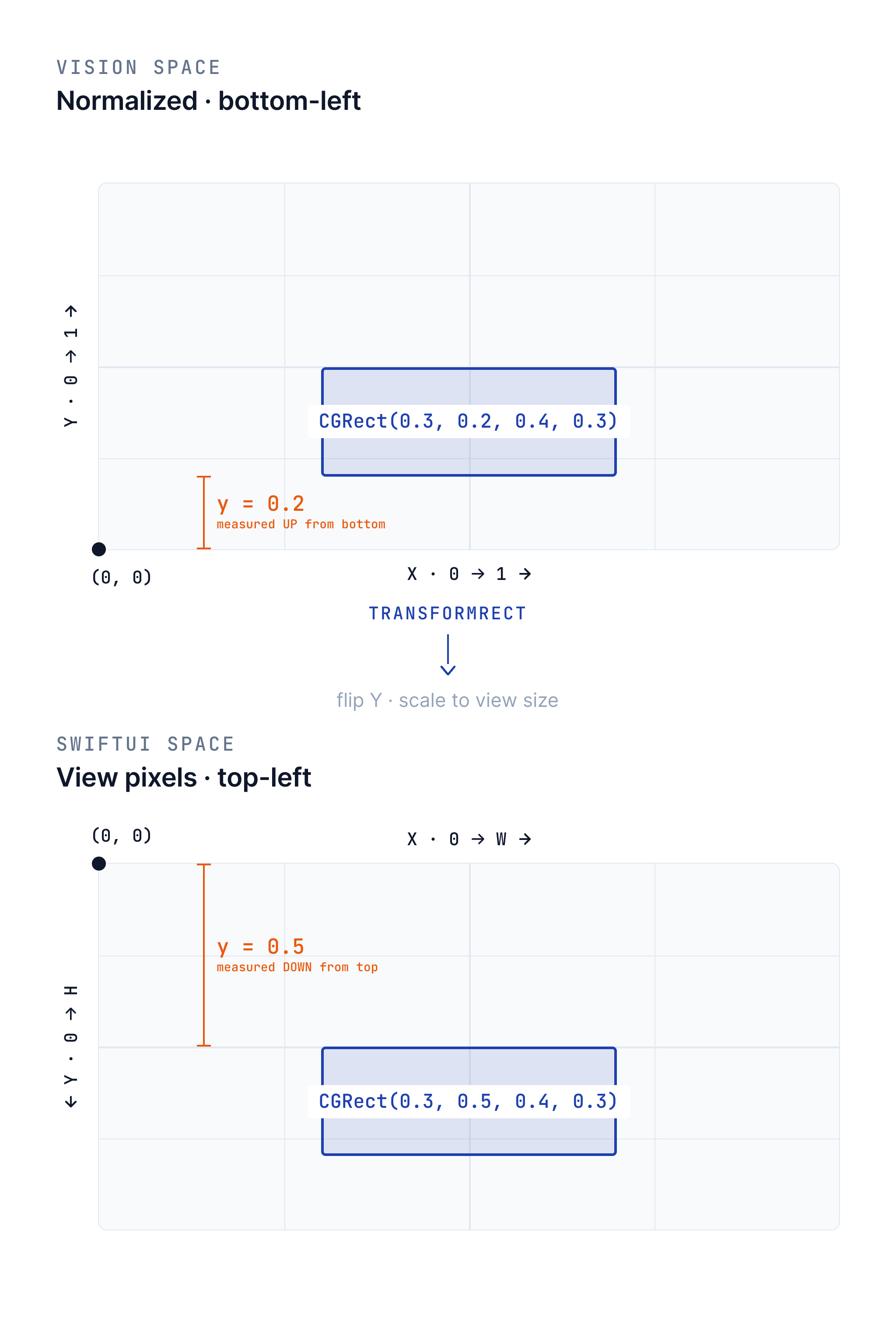
Bounding boxes from Vision arrive in normalized coordinates (0-1 range, origin at bottom-left). Stitch’s UI uses SwiftUI layout coordinates (origin at top-left, sized to the view). The shared transformRect helper bridges this gap, flipping the Y-axis and scaling to the target view size in a single pass. This same math is reused across every vision node in the system.
It worked in my demo. Why was production drifting?
This was one of the more instructive debugging episodes I worked through. The setup: I had built a standalone demo app to prototype object detection, and it rendered bounding boxes perfectly aligned with detected objects. But Stitch’s overlay drifted – especially when tilting the device along the Y-axis.
The Three Differences
The tricky part was separating “what differed between the demo and Stitch” from “what actually fixed Stitch.” The reference demo and Stitch differed in three places, but only one of those variables changed in the final fix:
| Aspect | Reference demo | Stitch before | Stitch after | Result |
|---|---|---|---|---|
| Rendering | GeometryReader + Path |
Rectangle().position() |
GeometryReader + Path |
Root cause |
| Buffer source | Direct pixel buffers | CIImage conversion |
CIImage conversion |
Ruled out |
| Overlay target | AVCaptureVideoPreviewLayer |
SwiftUI Image |
SwiftUI Image |
Ruled out |
The last column is the important part. Buffer conversion and overlay target were differences between the known-good demo and Stitch, but they stayed the same when Stitch was fixed. That ruled them out. The drift disappeared only when Stitch stopped drawing the already-converted box with Rectangle().position() and started drawing it with explicit coordinates in a Path.
The Fix
The fix was to adopt the GeometryReader approach and the transformRect(fromRect:toViewSize:) helper that flips the Y-axis and computes size/position offsets in a single pass. This math became the standard coordinate conversion used throughout Stitch’s vision pipeline – the same helper that the CoreML and QR nodes now rely on.
The Value of a Reference App
Building the standalone demo app wasn’t just useful for prototyping – it became the debugging tool that cracked the alignment problem. By having a known-good implementation to compare against, I could systematically isolate each variable (rendering approach, buffer source, overlay target) until the root cause was clear. This is a pattern I’d use again: when production behavior diverges from expected behavior, build the simplest possible version that works, then diff the two.
This is one of four posts about my work at Stitch. See also: Building a 3D System Inside Stitch, Bringing AR to Stitch, and Building StitchAI.